Connecting Land Warfare Teams with Tactical Communications
It is probably fair to say organized conflict pre-dates the emergence of homo-sapiens, and perhaps our bigger, specialized brains enabled superior ability to communicate and drive our evolution and means of warfare. There are only several hundred generations of recorded human history, often delineated by major conquests, wars, dynastic changes, etc. Each of these relied on something fundamental, but not trivial: effective communications.
The thoughts, ideas and plans of leaders and generals could not manifest themselves without communication, verbal and/or written, disseminated with clarity and scope. For the case of military tactical communications, speed and security are equally important to the command and control of forces.
Read more about Tactical Communications Antenna products here.
Analog Communications of the Past
Historically, the ability to discern and understand shouts, drum beats, flags, and signal fires encompassed battlefield tactical communication. Messages by foot, horseback and pigeon could carry voluminous communications, but with significant lag between send and receive. Imagine what a revelation telegraphy was to tactical communications in the late 18th century (French optical telegraphy) and then electrical telegraphy and Morse Code in the 19th century! But, even with wired telegraphs and the early wireless telegraphy of WWI, the ancient methods were relied upon:
Du hast 3 ungelesene Nachrichten…
(You have 3 unread messages…)

Unfortunately, the war-to-end-all-wars was anything but, and it hastened the development of wireless communications as telegraphy cables and systems were destroyed around the world.
Early Radio Communications
Early radio technology used simple waveforms at low frequencies (tens to hundreds of kilohertz) which provided low information carrying capacity (bandwidth). After the discovery that ‘shortwave’ radio at HF frequencies could be heard across and beyond continents by signals reflecting off the ionosphere, such wireless communication quickly emerged as a serious competitor to transoceanic cable for commercial and governmental communication. For military communications, shortwave became extremely important for keeping in close contact with various echelons of command and control, all the way back to HQs and capitals. At shorter wavelengths of VHF frequencies, radio technology also advanced rapidly to enable communications at closer range, using transmitters small enough for vehicles, planes and even soldiers.
The rapid maneuver warfare tactics of WWII would not have been possible without the swift advance of tactical communications radio technology for long range and short range two-way communications. After all, there could be no ‘blitz’ with the ‘kreig’ if motorized infantry, tanks, and aircraft could not communicate to coordinate actions!
Decades later, these fundamentals still apply.
As the electromagnetic spectrum’s importance grew, governments around the world regulated the use of various frequency bands, because narrow bands of frequency were required for each channel of communication - and interference between systems and channels was a big problem. The capacity of frequency modulated radio channels was far too low for the needs of two-way wireless users.
Important Innovations
Two technologies of the late-middle of the 20th century saved the day: cellular telephony (Bell Labs) and packet switching over radio channels (ALOHANET). The parallel development of ARPANET and satellite communications led to the internet protocol (IP), Ethernet and transmission control protocol (TCP) — creating the global communications revolution we enjoy today. So evidently, the ’60s and ’70s weren’t just about the space program!
Modern militaries widely rely on radio frequency (RF) technology for voice and data services at every level for command, control, communications, computers, combat systems, intelligence, surveillance, and reconnaissance (C5ISR). The need for ad-hoc military communication nets for short, medium and communications, radio systems are myriad and complex, operating across HF, VHF and UHF frequency regimes on land, sea, air, space and cyberspace domains.
Modern Equipment Challenges and Success
The high cost of military communications gear means long service life is required; while the need for interoperability among myriad protocols and frequency bands means modern radios must be extremely flexible and capable. Creating new fully-compatible and capable tactical communication systems is not easy, as proven by the failure of the Joint Tactical Radio System (JTRS) program in the 2000s.
Despite JTRS, the solution to this complexity and challenge is employing software defined radio (SDR) technology to create the links shown in this battlefield tactical communications architecture rendering.
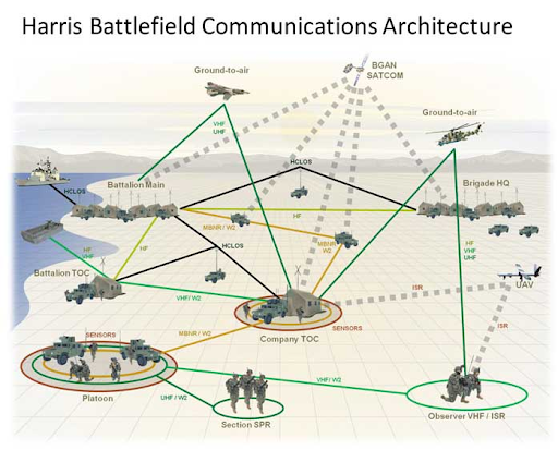 Source: www.harris.com/perspectives/modernizing-the-battlefield/the-case-for-software-defined-capabilities
SDRs provide strong benefits for “rapidly changing and highly complex battlefield, extending to airborne and terrestrial radios, electronic warfare, and space systems. The ability to upgrade and update existing software to meet and beat new and emerging threats gives warfighters the combat edge.” Support for lots of waveforms in one unit, such as SINCGARS, HAVE QUICK I/II, LINK-16, MANET, SRW, WNW, SATCOM becomes possible with SDR. Some successes have emerged, such as the HMS and Rifleman Radio products.
Satellite Systems and Communications
Satellite systems are very important to modern military communications for their ability to handle large numbers of users over a wide area and provide high-bandwidth data channels. The high tempo of operations relies on the data bandwidths SATCOM provides. Without it, warfighting capability is severely constrained.
Software-defined radios offer great design freedom to the radio signal processing engineer -- while making the job of the defense RF electronics and antenna engineers more challenging as frequency bandwidths increase amidst size, weight, and power plus cost (SWAP-C) constraints. Most tactical radio systems and networks rely on omnidirectional antennas that must be optimized for platforms and use cases.
What You Need to Know Before Selecting an Omnidirectional Antenna
Antennas are everywhere, in numerous types and form factors, at various price points, for many markets.
Antenna Basics
Antennas transform electric currents in conductors to radiating electromagnetic fields or vice versa, typically at frequencies related to the size of the antenna. The simplest are omnidirectional meaning they work somewhat like a traditional light bulb, producing light all around the bulb.
Learn about the five essential specs you need to know when choosing an Antenna, here.
Let’s start with the humble dipole, formed by two ¼ wavelength long conductors connected to the ‘hot’ and ‘ground’ of an RF circuit. To make a 300 MHz dipole, the overall length would be 0.5 meters, i.e. two 0.25 meter arms mated to the feed point at their ends. This creates a so-called center-fed dipole antenna.
So how does such a simple structure couple an electromagnetic field around it? We’ll try to explain, but you’ll probably benefit more from watching this fantastic old school educational film (seriously it’s good).
One thing to get out of the way up front is that antennas are reciprocal, meaning that an electromagnetic field impinging on an antenna will create an electric current in the antenna required for it to radiate the same way when excited by that analogous electric current. Hence, although the term radiation implies energy leaving the antenna as electromagnetic radiation, it also describes the way a radio wave interacting with an antenna will create currents in the RF circuit.
For our purposes, let’s stick with a transmission scenario.
RF transmitters produce oscillating electric currents at the frequency they are tuned to. The form of the oscillation is a sinusoidal variation of the amplitude of the voltage, centered around zero volts. For our ½ meter dipole, a transmitter creating a 300 MHz standing wave of positive and negative currents (I) in the antenna, also creates corresponding changes in voltage (V) as determined by Ohm’s law (V=I*R). These changing currents and voltages generate electric and magnetic fields that are in time-quadrature (see the video), and travel out from the antenna.
Defense and Security Radio Systems
Most radio systems for defense and security are designed for optimal performance at 50 Ohms real impedance (no complex component). From the perspective of the transmitter, an antenna looks like a ‘reactive’ load that can be modeled as a complex combination of resistance, capacitance and inductance as a function of frequency. Antennas rarely meet this ideal 50 Ohm standard, except for narrow frequency range of operation inherent to certain designs and/or painstakingly optimized antennas — described as ‘matched.’ Indeed, an ideal dipole is a 73 Ohm radiation resistance device, while a monopole operates ideally at 37 ohms. 50 Ohm RF design is a convention to split this baby.
There are several ways to illuminate this impedance behavior, most often as a graph of Voltage Standing Wave Ratio (VSWR) which is another way to state the return loss of an RF device or antenna. See this excellent explanation or check out our blog post that makes fun of the counter-intuitive terms used.
Antenna Radiation
Now let’s explore how antennas radiate.
The relative strength of the electromagnetic field around the antenna is determined by the type of antenna and its design. For a dipole, the omnidirectional radiation of the E-field is the same in all azimuthal directions of the plane perpendicular to the antenna axis (also-called boresight), maintaining circular symmetry but diminishing to near zero in the direction of the ends of the antenna (the so-called nulls).
So, a dipole’s radiation is not quite as isotropic as a lightbulb, but pretty close. In fact, antenna engineers compare the radiation strength of a dipole to a mythical isotropic radiator, and state the ideal dipole’s boresight gain, or relative strength, as 2.15 dBi (decibels with respect to isotropic), i.e. 1.64 times more than uniform radiation in all directions as seen in this diagram.
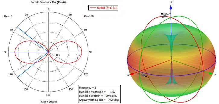
Source: https://cst2cd.acceptance.brimit.com/academia/examples/wire-dipole-antenna
Another common type of omnidirectional antenna is the monopole. By connecting the ‘hot’ side of the RF feedline to a ¼ wavelength wire and the ‘ground’ to the platform, or a so-called counterpoise, an effective compact antenna is created. The counterpoise, when not Earth itself, also known as a ground-plane, is typically composed of ¼ wavelength radials or a conductive screen or plate perpendicular to the ¼ wavelength wire.
When a monopole is constructed on a perfect perpendicular ground-plane, electromagnetically, it forms an image antenna that together mimics a dipole as shown diagrammatically here.
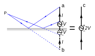 Source: https://en.wikipedia.org/wiki/Monopole_antenna
Because a monopole radiates only in the space above the ground-plane, it has twice the strength compared to a dipole, 5.15 dBi (i.e 2.15 for a dipole plus 3 dB to double to monopole power). Correspondingly, a monopole’s characteristic impedance (so-called radiation resistance) is half of a dipole.
As is often the case, the ground below a monopole is not perfect, which manifests as radiation pattern that ‘lifts’ from the horizon and reduces gain depending on the quality of the ground conductivity. See the diagram below showing a modeled HF monopole’s sensitivity to real-world ground conditions encountered by radio operators.
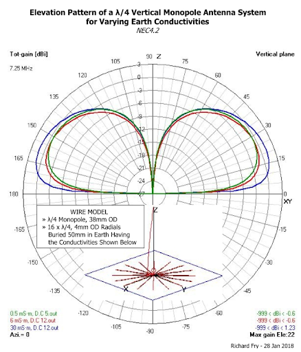
Source: https://broadcastengineering.info/viewtopic.php?t=6276
Such are the two types of omnidirectional antennas traditionally encountered in tactical communications systems. Deciding whether to choose a monopole or dipole for a particular platform and communication system depends on the concept of operations and other factors like co-siting of other antennas and the ability of the platform to form a suitable counterpoise. In general, handheld and manpack radios get monopoles, while fixed site and portable applications get dipoles. Vehicles can get either.
Finding an Omnidirectional Antenna
So you want an omnidirectional antenna. Should be easy to find what you need, right?
Maybe, but probably not -- without a fair amount of expertise and/or a list of the right questions to ask and specifications to cover. Let’s narrow things down via a series of questions.
1. Is the antenna for receive-only, or for transmitting low, moderate or high levels of power? BTW, transmit antennas can generally also receive, so you get that for free. Most tactical communications antennas fall into the moderate power (scores of watts) transceive variety.
2. What platform will the antenna mount to?
Although some omnidirectional antennas can be used on many structures, they are usually optimized for handheld, manpack, vehicle, tactical portable or fixed site platforms — but there are also naval, airborne and spacecraft omnidirectional antennas!
3. What’s the frequency of operation? And for transmit, what’s the maximum continuous power the transmitter will output; and what maximum VSWR can it tolerate?
Choosing an antenna that works for all frequencies and power levels expected is paramount for the aerial’s survival while providing the transmitter a sufficiently well-matched impedance keeps reflected power below levels that can damage its amplifier.
4. What gain and radiation characteristics are required? Relatedly, is a ground-plane dependent or independent omnidirectional antenna desired? Omnidirectional gains are typically about 0 to 2 dBi within 20 degrees above and below the horizon for antennas of standard dimensions (½ wavelength for a dipole, ¼ wavelength for a monopole). Wideband omnis can have gain as low as -20 dB at the low-end of their frequency range for practically sized structures. Some high gain omnidirectional antennas can obtain gains of 4 to 8 dBi, while their radiation patterns are compressed to ten degrees or less above and below the horizon.
Receive-only nearby field strength limits should be considered.
Reducing Electromagnetic Signature with Directional Antennas
With half the human population using smartphones, highly sophisticated electronic technology is so commoditized and ubiquitous, it has become almost blase. Contrast this with military communications technology, which although sophisticated, is much slower to evolve -- while being hugely important to maneuver and multi-domain warfare. Assured and secure tactical communications is a must for effectively prosecuting a fight, but can also be a vulnerability our clever foes exploit.
Communications spans all military echelons, using a mix of radio nets, wireless local area networks (WLAN) and strategic (satellite) communications that form a tactical internet. The diagram below depicts the US Army’s recently demoted WIN-T network.
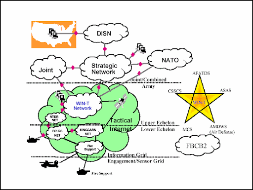
Source: https://www.globalsecurity.org/military/library/policy/army/fm/4-93-52/appa.htm
Besides the fact that WIN-T networks are way too complicated and slow-to-commission, lower Echelon tactical radio nets and WLANs are mostly omnidirectional affairs, meaning the antennas they use radiate in all directions. This is great for general purpose connectivity with friendly forces, but cannot prevent equal strength signals heading towards foes. This is a fundamental architectural and technological challenge of tactical communications today.
Our peer adversaries have invested heavily in electronic warfare to attack this vulnerability of western defense communication structures. Witness the conflicts in Ukraine and Syria. There’s plenty of talk about what Russian EW accomplished in Ukraine, see here. Syria has also been a place for Russian mischief.
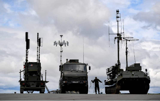
Russian Jamming system R-330ZH "Resident" and the electronic warfare system RB-301B "Borisoglebsk-2”Photo source (citing TASS article): https://www.veteranstoday.com/2018/09/28/electronic-warfare-comes-to-syria-israel-and-us-out-of-their-depth/
So what can our military communicators do when faced with adversary signals intelligence, jamming (electronic attack) and offensive cyber operations delivered over the air?
1. Reduce Susceptibility - orient directional antennas away from the adversary, preferably pointing radiation pattern nulls towards red forces. A null or reduced gain in the direction of the adversary has multiple benefits. Incoming electronic attacks are diminished because less power from the enemy jammer reaches the friendly receiver. Conversely, transmitted signals from the friendly radio with a directional antenna pointed away from the adversary will be lower power than an omni antenna transmission, and thus less detectable by adversary signals intelligence gear.
2. Increase ERP - orient directional antennas towards friendly forces to improve communication link budgets versus what an omnidirectional antenna can provide. A few dB of antenna gain can result in communication range improvement, or if long range is not required, transmitter power could be lowered, further reducing electromagnetic signature to the adversary.
To visualize the effects of a directional versus omnidirectional antenna, take a look at this graph of azimuthal radiation patterns for vertically polarized directional and omnidirectional antennas.
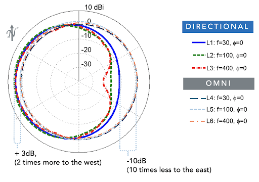
Comparison of directional and omnidirectional radiation patterns as obtained by a log-periodic dipole array and wideband dipole antenna operating over the same VHF frequency rang.
You can clearly see the benefit of directional antennas in tactical situations, assuming your friends and foes are in generally opposite directions. Notice in the illustration how a log-periodic dipole array antenna (LPDA) covers a wide arc with power levels at or above a dipole, over almost north to south, and as much as 3 dB more to the west. While in the eastern direction, radiated power is significantly diminished, from several to tens of dB (remember -20dB equals 0.01, or 1/100).
Reducing Electromagnetic Signature in Practice
How about a practical application to cement these concepts. What if you wanted to change a military tactical vehicle’s radiation pattern from equal-in-all-directions (omnidirectional) to favoring transmit to the rear while reducing forward transmission and reception?
This could be very useful for a tip-of-the-spear vehicle like the USMC Assault Amphibious Vehicle (AAV) seen here with its barely visible omnidirectional monopole antennas:
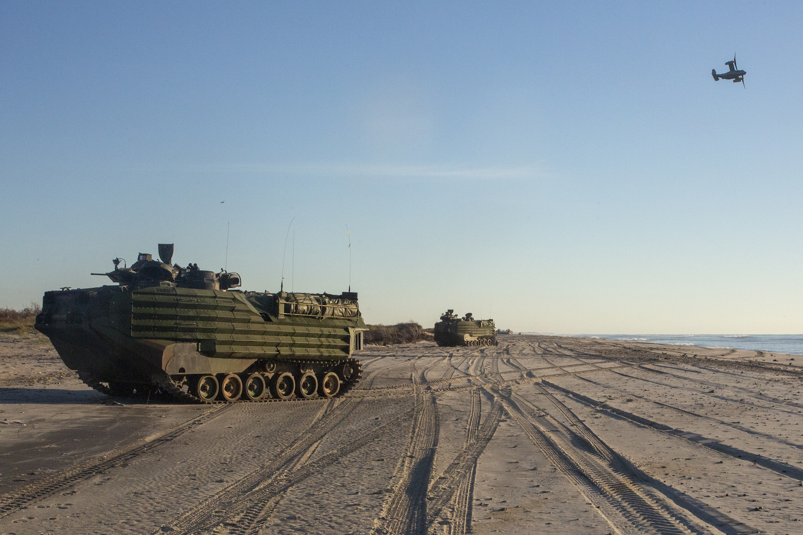
Source: DVIDS, SSgt Andrew Ochoa, https://www.dvidshub.net/image/4865424/comptuex-amphibious-assault
There’s another type of wideband directional antenna called the log-periodic monopole array that provides the same radiation pattern benefits as an LPDA. When placed on the centerline of the top of an AAV with the shortest elements towards the rear, the pattern would look roughly like the sketch below.
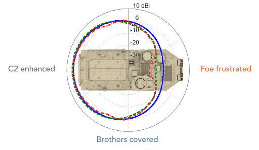
Illustration of the radiation pattern of a directional antenna mounted atop an AAV
When communicating through a directional antenna like this while assaulting foes in front of the vehicle, the electromagnetic signature of the AAV would make it harder for the enemy to detect its signal emissions and jam its communications, while enhancing communication with the rear echelons without hurting communication with other elements in the assault team in the flanks.
Check out this blog post for more on how to Communicate like a Pro...
Not only is this a slick use of electromagnetics, it also gives a really cool look:
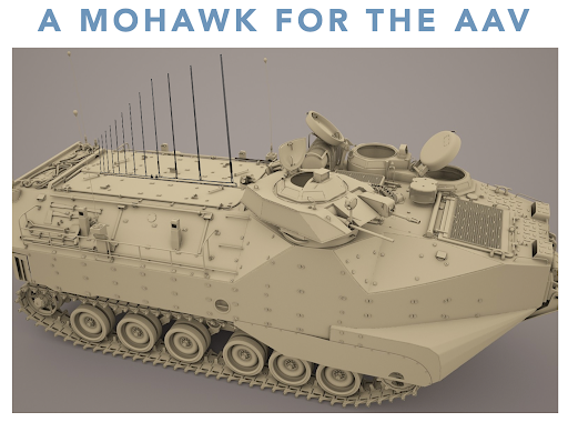
One special antenna added to the AAV can change its electromagnetic signature for VHF, reducing susceptibility to enemy EW while enhancing communications with USMC command & control plus preserving tactical communications.