


A previous blog post introduced the hybrid loop-Adcock antenna, which, in a crossed configuration, is excellent for Watson Watt (WW) radio direction finding. A simple WW implementation can make angle of arrival (AoA) estimates by calculating the arctangent of the magnitude of the EW/NS signal ratio. Problem is, there is at best a 180 degree AoA ambiguity.
Watson Watt Processing and Direction Finding
Consider this plot of normalized signal amplitudes from an idealized Adcock-type DF antenna that makes signals suitable for Watson Watt processing: a NS channel, EW channel and OMNI channel.
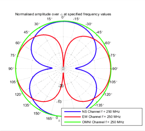
If you wanted to create a simple means of determining which direction a signal arrived from using these amplitudes, the OMNI signal is clearly useless. But taking the ratio of EW and NS channels and computing an arctangent, you could determine the angle within one quadrant that the signal arrived from. A signal from 45 degrees has a ratio of about 1. Recall arctan(1) = 45 degrees. For signal ratios >> 1, angles approach 90 degrees, while for ratios << 1 angles approach zero.
But EW/NS = 1 has four angles at which it occurs: 45, 135, -135 (225) and -45 (315) degrees. That's 90 degree ambiguity. For other angles, the arctan calculation and which signal is greater can reduce the ambiguity to a 90 degree sector on either side of the plane, but that is still not particularly useful.
All is not lost, because there is more information available: the phase of the signals.
The plot below shows the phase of the NS and EW channels with respect to the relatively constant OMNI channel phase as a function of angle of arrival.
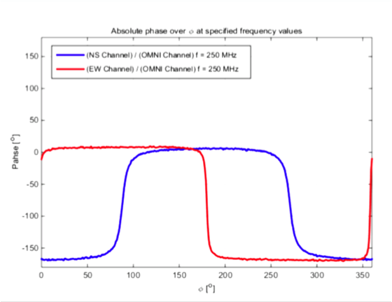
Now this plot is tantalizing -- there is a unique NS and EW phase combination in each quadrant. A cleverly designed WW algorithm can use this phase information to remove the quadrant ambiguity and calculate the signal's unique angle of arrival regardless of its source direction.
Note, in order to determine this phase information in sufficient form, the NS/OMNI and EW/OMNI ratio must yield a phasor volts result. In other words, they must be coherently measured at the same time.
How to Direction Find with Watson Watt Processing
So let's get on with a description of how to DF with Watson Watt signal processing.

First, let's start with some conventions.
Cartesian vs Map Angles
Oddly, map makers and mathematicians have chosen different ways to represent angles. This can cause confusion when transforming angles of arrival (Cartesian standard angles) calculated by the DF algorithm into map angles (headings). I suppose it may have something to do with the sun rising in the east and setting in the west -- nevertheless, here's a diagram to help illuminate the Cartesian convention used by the Alaris Watson Watt DF antenna products.
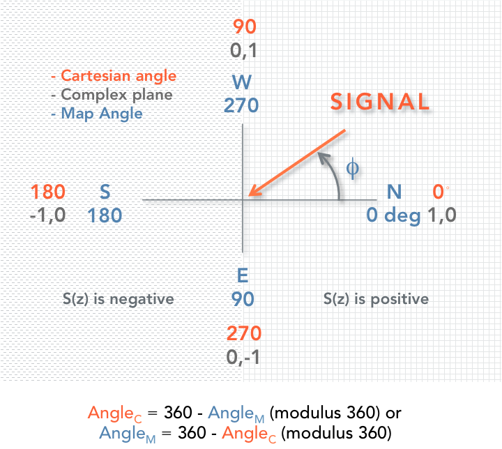
There's a neat trick to get an angle in the other domain using modulo arithmetic. To convert from Alaris Cartesian angle to map angle or vice versa, simply subtract it from 360 degrees and compute the modulus of 360 degrees. Easy as pie! Try it with the Excel function =MOD(360-A1,360), where A1 is the cell number for where the angle to transform is located.
The Complex Plane and Phasors
There's another important concept in the diagram above that greatly aids the direction finding algorithm ahead: the complex plane. Engineers and physicists love the complex plane and related phasors (vectors in the complex plane) for representation of circular or periodic systems.
It is important to recall that the magnitude of a phasor is positive in the right half of the complex plane and negative in the left half. Also phasor arithmetic comes into play with calculating the angles that result from the phase relationships of the DF antenna signals.
Interpreting the Watson Watt DF Algorithm
Now, finally, let's get on to our modern interpretation of the Watson Watt DF algorithm. As above, the three key signals are the phasor voltage signals that emerge from the Adcock direction finding antenna:
- VEW, influenced by signals mostly from East and West
- VNS, primarily influenced by signals from North & South
- VOMNI, similar output regardless of signal direction

This table requires a good long stare to understand... even then, examples are needed to cement the process and comprehension. Refer to the graphs, equations and results in the graphics below for an in-depth look.
An Example
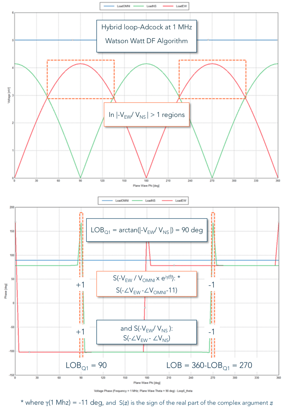
First, let's examine some representative 1 MHz data for a hybrid loop-Adcock DF antenna where the magnitude of VNS equals or exceeds VEW.
Per the table above, it is necessary to calculate ΦQ1 and the sign of the phasor relationships listed. Actually, to get the sign only requires paying attention to the phasor angles and calculating properly to determine which half of the complex plane the phasor lands in. It is also necessary to account for the phase normalization factor γ, which is -11 degrees at 1 MHz for this example. 
When you do everything right, even when ΦQ1 = 45 degrees (when VEW equals VNS) the truth table of signs allows the 90 ambiguity to be resolved as shown above. In this actual case above, ΦQ1 is 44 degrees to show the signal being resolved into each quadrant in the correct manner.
At the risk of overwhelming, the graph below shows the procedure for when VEW exceeds VNS, and when the LOB is on a large phase transition for one of the DF signals.
Even when there is a flip of phase for one of the DF signals, the algorithm remains robust. Try some values either side of the flip to convince yourself. Pretty slick!
Relevant DF Antennas
So you might ask, what antennas are designed to use this DF algorithm technique? 
Check out the DF-A0257 manpack/mobile DF antenna that delivers better than 5 degrees AoA accuracy for Watson Watt processing in a 14.6" x 3.8" diameter RF package. Its lower 20-400 MHz band is constructed with a hybrid loop-Adcock array to enable practical DF operation in the tough to accomplish 20-100 MHz regime. A somewhat larger version of this design approach for vehicles, DF-A0111, provides even better H/VHF sensitivity. Each antenna can use Watson Watt or three channel correlative DF techniques and each contains internal band switching, RF chain calibration noise source, digital compass and GPS antenna. An impressive package of state-of-the-art RF electronics!
Should you like to find out more about this new technology, Let’s chat to align your needs with a great solution.
