


Early Direction Finding Innovation
One early Direction Finding (DF) antenna innovation that stands the test of time is delineated in Frank Adcock's British Patent 130,490 entitled "Improvements in Means for Determining the Direction of a Distant Source of Electro-magnetic Radiation," granted in 1919. Its key attribute is rejection of horizontally polarized signals in its vertically polarized array of monopoles or dipoles.
Vertically polarized mono/dipoles
This arrangement helped operators solve the "night problem" for loop antenna HF direction finders, which were susceptible to the sky-wave signals produced by reflection off the ionosphere after dark, and by horizontally polarized signals in general.
Early Limitations and Solutions
Such an early invention was limited by the rudimentary radio electronics available at the time and a drawback of the approach, an inherent 180 degree ambiguity in the indicated direction of arrival (DOA) of the signal.
About a decade later, the ambiguity problem was solved by R A Watson Watt and L H Bainbridge-Bell (who both went on to become pioneers in radar, creating the Chain Home system that helped win the Battle of Britain in WWII).
As seen in the diagram below from BP 305,250, granted in 1929, they added an omnidirectional sense antenna and a clever bit of electronics (really analog computing) to exploit the phase of the DF and omni antenna signals to enhance or dim the oscilloscope beam in just the right way to remove the 180 degree DOA ambiguity.

Watson Watt Loop Antennas
Watson Watt's patent drawings showed loop antennas, despite the technique encompassing any non-directional antenna plus a directional antenna (or a system that can do both). Perhaps loops were shown to separate from Adcock's patent, and perhaps for their superior gain at electrically small antenna size. But crossed loops' mixed-polarization susceptibilities restricted their use in practice.
Adcock dipole and monopole arrays proliferated, and are widely used today. US armed forces use this VROD portable direction finder with Adcock array, for example.
The Best of Both Worlds
What if you want to get the benefits of higher gains possible with loops (allowing for much lower frequency operation), reduce cross-polarization errors to acceptable levels, while packaging the direction finder antennas in a less recognizable form factor? This is a tall design order!
Enter an invention by C A W Vale, CTO of our supplier, Alaris Antennas. Chris's innovation combines the best of dipoles and loops into an 'Adcock' configuration that vastly outperforms its namesake for Watson Watt or correlative direction finding signal processing techniques.
Hybrid Loop-Adcock
As described in European Patent EP2771943B1, the antenna, dubbed hybrid loop-Adcock, is a clever mashup of loop and dipole antennas along with anti-phase dual-feed tricks that make an excellent wideband and sensitive DF antenna element. Its array topology is seen in the diagram here.

This PAPER contains a detailed description of the hybrid loop-Adcock approach and results.
Benefits of the hybrid loop-adcock
A key accomplishment is the increased cross-polarization rejection by its the anti-phase dual-fed loop versus same-size standard top-fed loop, as seen in the graph below.
Concentrate on the bold dotted-red line for V-pol gain of the new design, at least 20dB above the green trace of a traditional Adcock array of the same size, while the dashed-red line shows the reduced susceptibility to H-pol signals for the anti-phase dual-fed loop.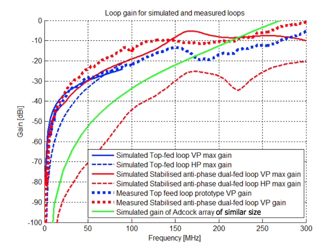
The second key attribute of this new design is superior sensitivity of the hybrid loop-Adcock versus pure Adcock array (each occupying the same volume), as seen below:

Note the 100 to 1000x (20 to 30 dB) gain improvement below 100 MHz of the hybrid loop-Adcock element over an equivalently sized Adcock array. This is a significant achievement, enabling the creation of compelling direction finding antenna systems that can pack accurate 20 MHz to 6000 GHz DF capability into compact form factors.
Relevant Products
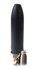
Check out the full SIGINT range DF-A0257 manpack / mobile DF antenna that delivers better than 5 degrees DOA accuracy for Watson Watt processing in a 14.7" x 3.6" diameter RF package. Its lower 20-500 MHz band is constructed with a hybrid loop-Adcock array to enable practical DF operation in the tough to accomplish 20-100 MHz regime. A somewhat larger version of this design approach for vehicles, DF-A0111, provides even better H/VHF sensitivity.
Each antenna can use Watson Watt or three channel correlative DF techniques and each contains internal band switching, RF chain calibration noise source, digital compass and GPS antenna. An impressive package of state-of-the-art RF electronics! Either of these DF antennas can achieve sub-degree DOA accuracy when using correlative interferometric DF techniques.
Should you like to find out more about this exciting technology,
Let’s chat to align your needs with a great solution.
