Radio direction finding (DF) is all about the angles... lots of them. Different conventions apply, specifics of implementation matter, and the potential for confusion abounds!
Calculating Line of Bearing
From the perspective of the direction finding antennas we provide, typical DF processor algorithms employed, and real-world mobile implementations, this post illustrates how to calculate the correct line of bearing to a signal of interest.
Tried-and-True... Sort Of
A reliable, always-on way to determine one's orientation is to use a compass that senses the earth's magnetic field. This ancient method is not fool-proof though, because the location of magnetic north and south migrate as the core of our planet changes over time. One also has to account for local differences between the direction the compass indicates as north (magnetic north) versus true north (the direction of the spin axis of earth).
The map and diagram below show the complex nature of magnetic field variation that must be handled in a practical DF system utilizing a magnetic compass.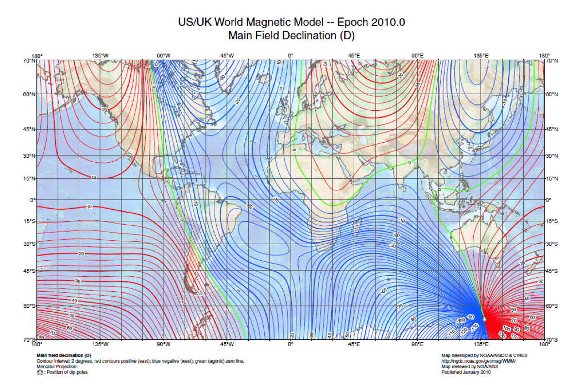
Fully unravelling the general-case magnetic declination adjustment—importantly, doing the addition or subtraction correctly—as well as accounting for grid variation (a map making oddity) is beyond the scope of this blog post. For our purposes, let's assume our DF system has a GPS receiver that indicates it is located in Memphis, Tennessee (where true north and magnetic north coincide), thus magnetic declination equals zero.
Determining Magnetic Heading
There's a cool gizmo in our Adcock DF antennas to provide magnetic heading, the Honeywell HMC6343 tilt-compensated electronic compass, with real-time digital output of about 2.5 degree RMS accuracy. This video shows the HMC6343 in action. Note that when the compass is rotated clockwise around its +Z axis, the heading angle increases. This is consistent with map angles, which are positive in the clockwise direction from North. Therefore, East is 90 degrees, South is 180, West 270 and so on.
DF antenna models DF-A0047, DF-A0069, DF-A0111, DF-A0120 and DF-A0201 each employ this compass to provide heading output by serial communications.
Digital Compass Offset
A detail to note is the orientation of the compass chip to the 'North' of the internal DF antenna construction, as seen in the diagram below for the DF-A0120 compact mobile DF antenna. 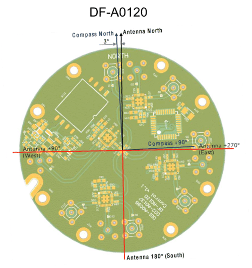 You can see that the compass is offset by 3 degrees to the DF antenna north. Practically speaking, if a DF120 were located in Memphis and oriented to point towards a signal of interest coming from true north, the DF algorithm would report angle of arrival (AOA) of the signal at zero degrees (more about this below) and the digital compass would output 357 degrees. Adding three degrees of digital compass offset corrects the bearing of the antenna to the correct bearing with respect to true north: Zero degrees, or mod360(360)=0.
For completeness, here are the digital compass offset angles for our readily available mobile Adcock DF antennas:
- DF-A0069 = 145.7 deg
- DF-A0111 = 145.7
- DF-A0120 = 3
- DF-A0201 = 0
- DF-A0257 = 0
- DF-A0254 = 0
Signal Processing
Let's switch gears to the Adcock antenna arrangement and DF processor's algorithm that processes their signals. For the full AOA details, please see this previous treatise on using Watson-Watt DF techniques. It is imperative for calculating lines of bearing to know that the DF algorithm reports angles of arrival per math/physics conventions, i.e. angles are in spherical coordinates and increase in value in a counter-clockwise direction...exactly opposite to the map angle convention.
Signal of Interest Line of Bearing
This means a DF-A0201 antenna/processor in Memphis pointing east with a signal of interest from true north produces two 90 deg outputs: the digital compass reads 90 degrees (due East), and the DF processor outputs an AOA of 90 degrees, meaning the signal is a quarter circle in the counter-clockwise direction—in other words, due north! Combining these two measurements properly produces a signal of interest (SOI) line of bearing (LOB) of Zero degrees.
The diagram below helps explain and reinforce the conventions and calculations.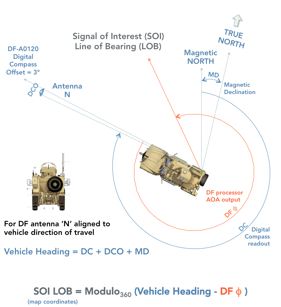
Now, let's put it all together using the diagram above for a DF-A0120 antenna on a notional tactical vehicle (with its north fiducial pointing forward) traveling roughly west from Lewisburg, PA where magnetic declination is about -11 degrees. A signal of interest is coming from the northwest.
Calculating SOI LOB
Our two electronic subsystems output the following:
Digital compass readout = 294 degrees
DF processor = 323 degrees
So what is the signal of interest line of bearing?
Use the formula!
SOI LOB = mod360(DC+DCO+MD-DFφ)
= mod360(294 + 3 - 11 - 323)
= mod360(-37)
= 322 degrees
i.e. Northwest
That's a lot of bother to come up with one number!
Quick SOI LOB thought experiment
Here's a thought experiment to cement the concepts. What's the SOI LOB for the scenario above, but with the vehicle traveling east?
It's 322 degrees! Kind of a trick question, because although the DF processor angle and digital compass outputs would change by minus 180 degrees, the SOI LOB calculation result remains unchanged:
SOI LOB = mod360(114 + 3 - 11 - 143) = mod360(-37) = 322
Conclusion
If I've failed miserably in explaining all this, please call me so I can apologize! Otherwise, give me a call about adding DF capabilities to your system. We can supply the DF antenna, DF processor, or both. It will be easy, I promise!