What do you do when a sensitive direction-finding antenna and a high-power transmitter antenna need to be close-by on the same platform? How can you assure the radiation emanating from the transmit antenna won’t kill the DF antenna?
Preventing DF Antenna Damage - An ESEA Question
This is a common dilemma for designers of systems that combine Electronic Support (ES) and Electronic Attack (EA) capabilities. To coin a phrase for this delicate endeavor: ESEA does it!
To figure this out, some physics is needed to describe what happens around an antenna from an electromagnetic field perspective, paying close attention to the geometry of the situation and the parameters of the antennas and transmitter employed.
Typical scenarios involve vehicle and manpack systems with transmit and receive antennas placed close to each other by necessity of the platform constraints.
Near and Far Fields
Keeping things simple, let’s focus on what happens in the vicinity of an omnidirectional antenna. Radiation around the antenna has different characteristics depending on distance from the antenna measured in wavelengths (λ) of the radiated signal, breaking roughly into the near-field region, transition zone and far-field region.
The diagram below illustrates these domains for an electrically small antenna (in other words, not horn, dish or panel antennas).
Near-field is the volume of space around an antenna less than about one wavelength in radius -- which is further divided into a reactive region (less than 0.16 λ) and a radiative region.
Lots of complicated interactions of the electric and magnetic fields happen in the reactive region, so for this post, we’ll concentrate on the radiative portion of the near-field, as well as the transition and far-field regions. A more general and excellent discussion of the near and far field transition zone can be found here: https://www.rfcafe.com/references/electrical/near-far-field.htm
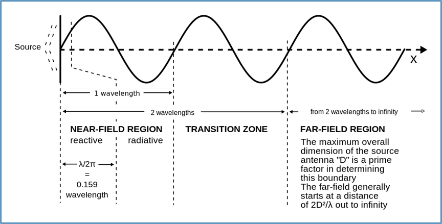
Figure 1 - Near and Far Field Region Definitions for electrically small antennas
from: https://en.wikipedia.org/wiki/Near_and_far_field
In the transition region between one and two wavelengths from the antenna, the electric and magnetic parts of the radiation begin to balance out. The far-field region, greater than 2 wavelengths from the antenna is where normal electromagnetic radiation wins out and the electric field strength per unit area falls in proportion to the square of the distance, by the equation:
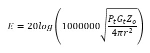
where for our purposes here, units of electric field strength, E, are dBmV/m, Pt is the transmitter power (Watts), Gt is the gain of the transmit antenna (dBi), Zo is the impedance of free space (equal to 377 Ohms), and r is the distance from the transmitting antenna (meters).
With this formula, we have a way to determine the field imparted by a particular EA system amplifier and transmitting antenna at a distance of radius r to the receiving antenna.
Well that’s nice…so what?
Accounting for the ES Antenna
We need to look at the other, ES, end of the problem to examine the highest field that the direction-finding antenna can survive before “something” breaks. This means we have to identify the components in each of the RF chains that have the lowest power handling capability, then work back to the received power at each of the antenna feed ports (NS, EW and OMNI in the case of a Watson-Watt or each port of an interferometer antenna) that would just exceed the destruction threshold.
We can then use the maximum gain of elements at each frequency to convert that received power (where the weakest component will break) to an E-field value of the incident signal. By doing this, we calculate the worst-case scenario over all elements. That is, for some frequencies of a Watson-Watt DF antenna such as the DF-A0257, the OMNI gain might have the highest gain of the three outputs, and the RF components in this chain will be at risk first. At other frequencies (and incoming azimuth), the NS might have the highest gain, putting the components in that chain at risk first.
Maximum E-Field
Such incident e-field limits are plotted as a function of frequency, as sees in the graph below. These always represent the most-conservative, worst-case scenario.
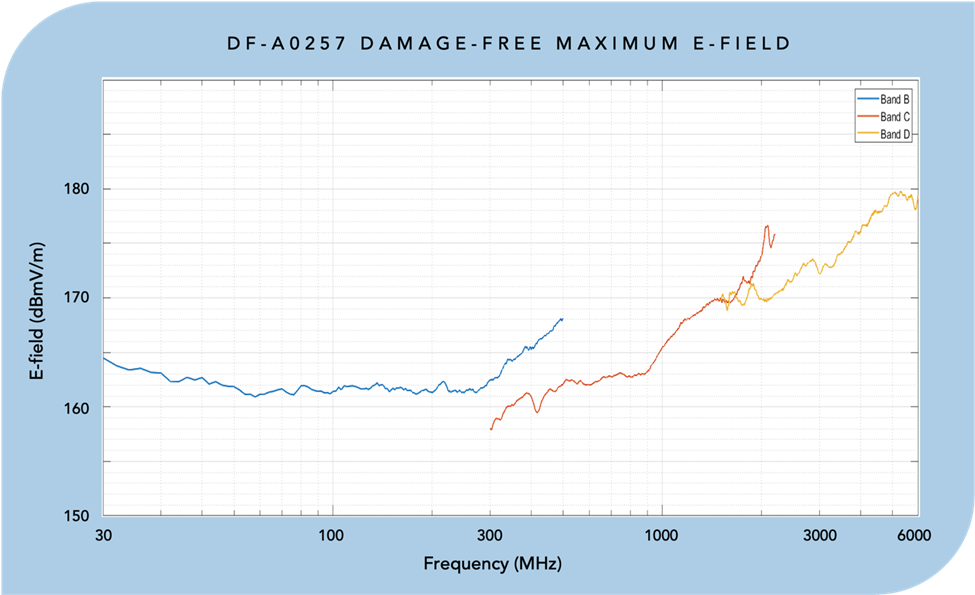
Figure 2 -Electric Field Strength Level of Destruction for DF-A057 Watson-Watt Direction Finding Antenna
In calculating the safe distance, you should calculate the maximum E-field as a function of distance for the transmitting device, and the DF-A0257 should be placed far enough away so that this induced E-field does not exceed the values in our plot. No additional knowledge about the DF-A0257 is needed for this calculation.
But, which frequency of operation should be used for determining the minimum safe distance?
Simple, choose the frequency with the lowest E-field value, which is 300 MHz. Reading off the graph, the damage-free maximum E-field impinging on the DF-A0257 antenna at 300 MHz is 158 dBmV/m.
ES and EA interaction
Putting all these concepts together, the table below can be used to locate a DF-A0257 antenna at a safe distance from a unity gain (0 dBi) transmit antenna, producing radiated power between 3 and 1000 Watts.
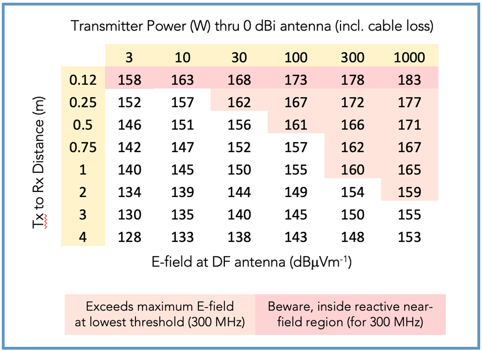
Deployment scenarios for DF-A0257 typically involve manpack systems or installations on vehicles. For each of these, it is interesting that upper levels of radiated RF power that are typically available and the dimensional constraints of each platform conspire to require careful attention to the maximum E-field of destruction of the receiving ES antenna.
For instance, a manpack chassis is generally about 37 x 30 x 15 (L x W x D) cm in size, so operating the EA antenna above about 20W may be a problem for antennas placed the maximum distance apart on its width (Note that the reactive near field region between antennas is within about 6 inches or 16 cm at 300 MHz).
Analogously, for a vehicle platform where hundreds of Watts may be available for omnidirectional unity gain transmission, a meter or more separation of the ES and EA antennas is warranted above 100W radiated power in order to operate without damaging the DF antenna.
By the way, the same considerations for antenna placement apply to other responsive receiver-transmitter systems, such as counter-IED or counter-UAS systems.
So, the bottom line for designing the ‘listen and shout’ systems is... ESEA Does It!
An aside
You may be wondering about the receiver electronics downstream of the ES antenna.
In the case of the DF-A0257 maximum power output from any of its three RF connectors will always be less than 21dBm. This is because the final stage amplifiers run into compression at internal power levels above 0dBm or so, and its maximum amplified power output is only 23dBm, followed by a 2dB attenuator, giving a max output of 21dBm.
Looking for support for your next antenna installation? Let's talk!